Theses
Topic description
Particle accelerators such as the synchrotron radiation source BESSY II, operated by the Helmholtz-Zentrum in Berlin-Adlershof, play an important role in basic research. For example, such sources enable the investigation and further development of solar cells and catalysts for green hydrogen or batteries.
The interaction of beams of charged particles with the vacuum chamber of particle accelerators is typically described in the frequency domain by the complex-valued and frequency-dependent beam coupling impedance. The broadest possible knowledge of the beam coupling impedances of particle accelerator components is of crucial importance, e.g. to avoid beam instabilities or excessive (local) thermal loading of the components.
Both the computer-aided calculation and the measurement of broadband beam coupling impedances in the laboratory are still a challenge. At the Helmholtz-Zentrum Berlin, the undulator department has set up a test stand for measuring undulators [1]. In simple terms, undulators can be thought of as large permanent magnets with periodically changing polarity. These are placed in the beam line and periodically deflect the particle beam in a transverse plane so that the charged particles radiate energy in a longitudinal direction.
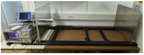
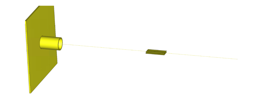
The test stand shown in Figure 1 is based on a Goubau line [2]. The enameled copper wire stretched from the left horn to the right plate is intended to emulate the beam of charged particles. To measure the undulators or undulator components, they are now placed in the test stand in such a way that the copper wire runs along the imaginary beam trajectory.The frequency-dependent reflection factor measured at the horn is used to estimate the beam coupling impedance of the respective particle accelerator component.
However, this reflection factor is not only determined by the properties of the structure to be tested, but is also significantly influenced by the properties of the test stand (geometry of the horn, distance between the plates, reflection at the plates).
The aim of the work is to investigate whether and how the properties of the structure can be calculated from the reflection coefficient. To this end, it will be investigated whether typical calibration methods known from microwave technology are suitable in principle, whether they may need to be modified or whether they are completely unsuitable for the application described above.
The work is supported by our partners M.Sc. Paul Volz and Prof. Dr. Atoosa Meseck from the Johannes Gutenberg University Mainz and the Helmholtz-Zentrum Berlin.
Tasks
- Familiarization with the topics of beam coupling impedance, Goubau lines and fundamentals of calibration methods from microwave technology
- Creating a simplified model to describe the high-frequency characteristics of the test stand
- Investigation of the propagation behavior of the electromagnetic fields along the Goubau line, e.g. depending on the aperture of the horn
- Evaluation of the suitability of common methods for calibration, so that the reflections measured at the test stand are largely determined by the particle accelerator component and not by the properties of the test stand
- If necessary, modification of existing methods for calibrating the reflections generated by the test stand
Keywords
algorithmics, high-frequency technology, field simulation, linear algebra
Type of work
Bachelor's thesis, Master's thesis (scope and level will be adapted accordingly)
Supervisor
Prof. Dr.-Ing. Thomas Flisgen
Literature
[1] P. Volz und A. Meseck, Impedance Studies for Elliptical In-Vacuum Undulator IVUE32, International Conference on Synchrotron Radiation Instrumentation, Hamburg, Germany, 2024
[2] B. Vaughn und D. Peroulis, “An updated applied formulation for the Goubau transmission line”, Journal of Applied Physics 126, 2019, https://doi.org/10.1063/1.5125141
[3] P. Volz und A. Meseck, “Goubau-Line Set Up for Bench Testing Impedance of IVU32 Components”, in Proc. IPAC’22, Bangkok, Thailand, July 2022, pp. 2719 – 2721 (https://accelconf.web.cern.ch/ipac2022/papers/thpopt053.pdf)
[4] P. Volz and A. Meseck, “Goubau-Line Set Up for Bench Testing Impedance of IVU32 Components”, J. Phys.: Conf. Ser. 2380 012026, 2022 (https://iopscience.iop.org/article/10.1088/1742-6596/2380/1/012026)
Topic description
Particle accelerators such as the famous Large Hadron Collider or synchrotron radiation sources such as BESSY II, PETRA IV and the Diamond Light Source play an important role in basic research. Particle collision facilities enable the characterization of subatomic particles, while synchrotron radiation sources are helpful, for example, in the investigation and further development of solar cells or catalysts for green hydrogen or batteries.
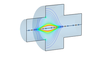
The interaction of beams of charged particles with the vacuum chamber of particle accelerators is typically described in the frequency domain by the complex-valued and frequency-dependent beam coupling impedance. Broadband knowledge of the beam coupling impedances is important, e.g. to avoid beam instabilities or excessive (local) thermal loading of the components. Figure 1 shows the electric field excited by a beam of charged particles in a simple test resonator.
Measuring broadband beam coupling impedances of particle accelerator components is a challenge. Typically, test stands based on a wire are used for this purpose [1-6]. However, the introduction of a conducting wire into the structure significantly changes its high-frequency properties. On the one hand, a transverse electromagnetic wave can propagate through the wire in the longitudinal direction; on the other hand, the wire represents a significant disturbance of the high-frequency resonances, where a high longitudinal component of the electric field strength on the axis is expected. However, precise knowledge of the beam coupling impedances of these resonances is particularly important.
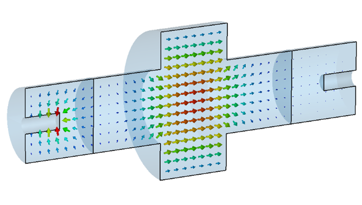
Recently, methods for the wireless measurement of beam coupling impedances have been proposed in the literature [7-9]. These methods do not require the insertion of a conductive wire into the structure. The high-frequency excitation is provided by couplers, which are attached to both sides of the structure (see Figure 2). These wireless methods appear promising as they overcome the above-mentioned disadvantages of the wired methods.
In this work, the properties of the wireless methods for highly resonant and for broadband accelerator components will be investigated by means of field simulations. The results based on scattering parameters are to be compared directly with the simulated beam coupling impedance. Advantages and disadvantages of wireless methods will be highlighted. The challenges of the concrete use of wireless methods in the measurement laboratory will also be considered.
The work is supported by our partner Dr.-Ing. Shahnam Gorgi Zadeh from the High Frequency Technology Group at CERN.
Tasks
- Familiarization with the topics of beam coupling impedance and the literature on wireless methods for measuring beam coupling impedances, including [7-9]
- Reproduction of basic simulation results in [7-9]
- Design of a resonant and a non-resonant test structure
- Creation of electromagnetic models of both structures
- Determination of the coupling impedances, in each case using wireless methods and directly using a numerical solver for beam coupling impedances
- Comparison of the results and working out the advantages and disadvantages of the wireless methods, possibly also in comparison to the methods based on a wire
- Discussion of possible difficulties in applying the methods in the laboratory
Keywords
algorithmics, high-frequency technology, field simulation
Type of work
Bachelor's thesis, Master's thesis (scope and level will be adapted accordingly)
Supervisor
Prof. Dr.-Ing. Thomas Flisgen
Literature
[1] P. Volz und A. Meseck, “Impedance Studies for Elliptical In-Vacuum Undulator IVUE32”, International Conference on Synchrotron Radiation Instrumentation, Hamburg, Germany, 2024
[2] P. Volz und A. Meseck, “Goubau-Line Set Up for Bench Testing Impedance of IVU32 Components”, in Proc. IPAC’22, Bangkok, Thailand, July 2022, pp. 2719 – 2721 (https://accelconf.web.cern.ch/ipac2022/papers/thpopt053.pdf)
[3] P. Volz and A. Meseck, “Goubau-Line Set Up for Bench Testing Impedance of IVU32 Components”, J. Phys.: Conf. Ser. 2380 012026, 2022 (https://iopscience.iop.org/article/10.1088/1742-6596/2380/1/012026)
[4] M. P. Sangroula, R. R. Lindberg, R. M. Lill und R. Zabel, “Measuring vacuum component impedance for the Argonne Advanced Photon Source upgrade”, Phys. Rev. Accel. Beams 23, Aug. 2020, doi.org/10.1103/PhysRevAccelBeams.23.082803
[5] S.Y. Kim, F. Stulle, C.K. Sung, K.H. Yoo, J. Seok, K.J. Moon et al.,“Characterization of the Goubau line for testing beam diagnostic instruments”, JINST 12 P12016, 2017, https://doi.org/10.1088/1748-0221/12/12/p12016
[6] V. G. Vaccaro, “Coupling impedance measurements: an improved wire method”, INFN, Rep. INFN/TC-94/023, pp. 1049–1052, 1994
[7] C. Antuono, A. Mostacci, A. Passarelli, C. Zannini, M. R. Masullo, and M. Migliorati, “A wireless method for beam coupling impedance bench measurement of resonant structures”, in Proc. 15th Int. Particle Accelerator Conf. (IPAC'24), Nashville, TN, USA, May 2024, paper THPC53, pp. 3124-3127.
[8] C. Antuono, M. Migliorati, A. Mostacci, and C. Zannini, “A Wireless Method for Beam Coupling Impedance Measurements of the LHC Goniometer”, in Proc. 68th Adv. Beam Dyn. Workshop High-Intensity High-Brightness Hadron Beams (HB’23), Geneva, Switzerland, Oct. 2023, pp. 407–410., doi:10.18429/JACoW-HB2023-THAFP05
[9] C. Antuono, M. Migliorati, A. Mostacci, E. Métral und C. Zannini, “A Wireless Method to Obtain the Impedance From Scattering Parameters”, in Proc. IPAC’22, Bangkok, Thailand, Jun. 2022, pp. 2213–2216, doi:10.18429/JACoW-IPAC2022-WEPOTK063


Topic description
Receiving and transmitting antennas on the outside of aircraft fuselages are indispensable for a wide range of aircraft communication, positioning and measurement systems. However, they can be disturbed by intentional and unintentional electromagnetic signals, e.g. by the electronics of passengers in the cabin or permanently installed aircraft electronics. The coupling between the antennas on the outside of the fuselage and the passengers' electronics depends largely on the aircraft geometry and the openings in the fuselage.
The aim of the work is to understand and quantify the coupling between the antennas on the outside of the fuselage with antennas inside the fuselage in the frequency range from 100 MHz to 5 GHz. Since the length of the electromagnetic waves can become significantly smaller than the dimensions of the fuselage, this is a challenging large electromagnetic field problem.
In order to gain a fundamental understanding of the coupling, simple numerical models, as shown in Figure 1, will therefore be examined first. Modeling the electronics of the passengers in the cabin as generically as possible plays a special role here. The overall aim of the considerations is to create reliable rules of thumb for estimating the coupling between the external antenna and the interfering radiators in the cabin. The validation of the numerical calculations as well as the analytical estimates with the help of high-frequency measurements in Hamburg at Lufthansa Technik AG are possible within the scope of the work.
Tasks
- Familiarization with existing literature on the subject of coupling antennas on the outside of the aircraft fuselage and antennas in the cabin
- Creating simple models to describe the high-frequency coupling between an antenna on the outside of the fuselage and an antenna inside the cabin for different frequencies in the relevant range
- Definition of a coupling metric that has as little influence as possible on the specific radiation characteristics of the antenna in the cabin
- Carrying out systematic parameter studies, e.g. varying the position of the antennas in the cabin, the size, shape and distance of the windows
- Comparison of the results with common worst-case estimates, e.g. based on the Friis transmission equation
- Investigations into the usability of area decomposition methods to reduce simulation times
- Definition of improved formulas for estimating the coupling between the antennas on the outside of the fuselage and in the cabin
- Validation of the rules of thumb using more complex models and measurements
Keywords
algorithmics, high-frequency technology, field simulation
Type of work
Bachelor's thesis, Master's thesis (scope and level will be adapted accordingly)
Supervisor
Prof. Dr.-Ing. Thomas Flisgen
Dr.-Ing. Kevin Erkelenz (Lufthansa Technik AG)
Literature
[1] M. Bachhuber, Analyse und Modellierung der Funkausbreitung in Passagierkabinen von Großraumflugzeugen, Dissertation Universität Erlangen-Nürnberg, Erlangen, Deutschland, 2011 (https://open.fau.de/handle/openfau/1701)
[2] G. A. Rasek et al., HIRF Transfer Functions of a Fuselage Model: Measurements and Simulations, in IEEE Transactions on Electromagnetic Compatibility, vol. 56, no. 2, pp. 311-319, April 2014, doi: 10.1109/TEMC.2013
[3] J. Schüür and R. R. Nunes, Determination of the path loss from passenger electronic devices to radio altimeter with additional EMI test, 2012 ESA Workshop on Aerospace EMC, Venice, Italy, 2012, pp. 1-5
[4] Jay J. Ely, Electromagnetic Interference to Flight Navigation and Communication Systems: New Strategies in the Age of Wireless, NASA Technical Report, 2005 (https://ntrs.nasa.gov/citations/20050232846)
[5] Adolf J. Schwab, Elektromagnetische Verträglichkeit, Springer-Verlag Berlin, Heidelberg 2011, doi: 10.1007/978-3-642-16610-5

Topic description
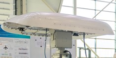
Satellite communication systems in the Ku- and K-/Ka-band are becoming increasingly important in commercial aviation. Radomes made of RF-transparent materials are used to reliably protect the required antenna hardware from external environmental influences such as moisture, temperature changes and mechanical stress. These radomes are typically additionally coated with paint systems.
Current developments are aimed at bringing radomes as close as possible to the antenna electrically or even integrating them directly into the antenna layout. One possible approach is to apply a coating system directly to planar antenna structures. Such integration concepts promise advantages in terms of weight, installation space, aerodynamics and thermal management. However, the radome and the coating system directly influence the near-field behavior of the antenna aperture. Precise knowledge of the dielectric properties of the paint used is therefore essential for an optimized antenna design.
The electromagnetic characterization of such coating systems in the Ku- and K-/Ka-band is to be carried out as part of this work. The aim is to experimentally determine relevant material parameters such as the frequency-dependent complex permittivity and make them available for use in simulation-based antenna designs. The work thus contributes to the optimized development of integrated antenna-radome solutions for satellite communication in aviation.
Tasks
- Literature research
- Overview of the topic of aircraft paint systems
- Measuring methods for determining dielectric material properties
- Implementation
- Selection of a measurement method
- Implementation of the method using suitable software (e.g. MatLab)
- Testing the software using simulation data
- Electromagnetic simulation
- Simulation of reference and test setups to verify the implemented algorithm
- Test setup
- Development of components (e.g. circuit boards) for testing
- Production including painting of the required components and test samples
- Test execution
- Measurements of the painted test samples using the developed procedure (e.g. using a network analyzer)
- Evaluation and comparison
- Summary of the advantages and disadvantages of the selected measurement method
- Evaluation of the measurement results
Keywords
Algorithmics, high-frequency technology, field simulation, measurement technology, material characterization
Type of work
Bachelor's thesis, Master's thesis, project work or internship (scope and level will be adapted accordingly)
Supervisor
Prof. Dr.-Ing. Thomas Flisgen
Dr.-Ing. Kevin Erkelenz (Lufthansa Technik AG)
Literature
[1] Rhode und Schwarz, Measurement of Dielectric Material Properties, Application Note 2012, www.rohde-schwarz.com/ae/applications/measurement-of-dielectric-material-properties-application-note_56280-15697.html
[2] Agilent Technologies, Basics of Measuring the Dielectric Properties of Materials, Application Note 2006, academy.cba.mit.edu/classes/input_devices/meas.pdf
[3] H. Suzuki und T. Hotchi, Microwave measurement of complex permittivity of a sheet material under test sandwiched between sheet metal and a calibrated stripline resonator, IEEE Instrumentation and Measurement Technology Conference, Victoria, BC, Canada, 2008, pp. 563-567, doi: 10.1109/IMTC.2008.4547100
[4] H. Suzuki, T. Hotchi und T. Nojima, A New Muasurement System for the Perpendicular Complex Permittivity to DUT Sheet by Stripline Simulation," IEEE Transactions on Instrumentation and Measurement, vol. 61, no. 9, pp. 2476-2482, Sept. 2012, doi: 10.1109/TIM.2012.2192334
[5] P. M. Narayanan, Microstrip Transmission Line Method for Broadband Permittivity Measurement of Dielectric Substrates, IEEE Transactions on Microwave Theory and Techniques, vol. 62, no. 11, pp. 2784-2790, Nov. 2014, doi: 10.1109/TMTT.2014.2354595
[6] K. Szostak und P. Słobodzian, Broadband Dielectric Measurement of PCB and Substrate Materials by Means of a Microstrip Line of Adjustable Width, in IEEE Microwave and Wireless Components Letters, vol. 28, no. 10, pp. 945-947, Oct. 2018, doi: 10.1109/LMWC.2018.2864196
[7] C. -C. Huang, C. -L. Peng, P. -Y. Lin, B. -H. Yang, K. -C. Cheng und W. -T. Fu, Dielectric Characterization of Printed Circuit Board by Microstrip Line Up to 110 GHz, 2019 Electrical Design of Advanced Packaging and Systems (EDAPS), Kaohsiung, Taiwan, 2019, pp. 1-3, doi: 10.1109/EDAPS47854.2019.9011652
[8] Y. Liu, S. Yong, J. Li und V. Khilkevich, Dielectric Constant Extraction for Microstrip Transmission Lines Based on S-parameter Measurements and Cross-section, 2021 IEEE International Joint EMC/SI/PI and EMC Europe Symposium, Raleigh, NC, USA, 2021, pp. 982-987, doi: 10.1109/EMC/SI/PI/EMCEurope52599.2021.9559371


Initial situation
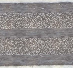
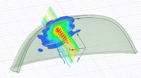
Radomes mechanically shield the antenna hardware from external environmental influences - a function that is particularly important in aviation, where extreme environmental conditions must be taken into account. Conventional antenna systems use radomes that are located in the far field of the individual antenna elements of the phased array. The antenna and radome are designed separately and mounted with a defined distance (air gap). New integration approaches aim to bring the radome electrically closer to the antenna system or to integrate it directly into the antenna layout in order to reduce weight, height and installation effort - particularly relevant in aviation applications with high requirements in terms of weight, aerodynamics and thermal management.
The focus is on two alternative integration concepts:
- Direct integration of flat radome layers with planar antennas in printed circuit board (PCB) technology
Here, the radome is located in the near field of the individual elements, which influences the radiation behavior, impedance matching and element coupling. - Coating the antenna PCB with a thin paint system
This approach offers great potential in terms of weight reduction and heat dissipation across the aperture surface due to the very low coating thickness of just a few 100 µm. At the same time, however, it lacks the mechanical protection provided by conventional radomes with flexible foam or hard coatings.
Tasks
- Literature research
- State of the art in radome and antenna integration
- Overview of suitable materials and coating systems
- Electromagnetic simulation (focus)
- Modeling and analysis of single radiators with integrated radome in the near field
- Investigation of impedance matching, directional characteristics and element coupling in the phased array
- Comparison of the two integration approaches with regard to beam shaping and swivel capability
- Analytical modeling
- Development of simplified models to evaluate the interaction between antenna and radome
- Mechanical investigation (optional, exploratory)
- Carrying out simple mechanical tests on antenna PCBs with/without radome structure
- Identification of basic requirements for the mechanical protection of the antenna system in aviation applications
- Discussion of the necessity of a radome as a mechanical protection system: Why can an antenna PCB not be exposed directly?
- Evaluation and comparison
- Summary of the advantages and disadvantages of both approaches in terms of electromagnetic performance and mechanical suitability
- Derivation of recommendations for the system architecture of future antenna solutions
Expected results
- Evaluation of the electromagnetic effects of different integration methods
- Basics for the mechanical requirement specification of an integrated antenna radome stack
- Decision support for the selection of suitable radome solutions in early system development
Keywords
Field simulation, high-frequency technology, antennas
Type of work
Bachelor's thesis, Master's thesis, project work or internship (scope and level will be adapted accordingly)
Supervisor
Prof. Dr.-Ing. Thomas Flisgen
Dr.-Ing. Kevin Erkelenz (Lufthansa Technik AG)
Literature
[1] C. A. Balanis, Antenna Theory: Analysis and Design, vierte Auflage, Wiley 2016
[2] Klaus W. Kark, Elektromagnetische Wellen auf Leitungen, im Freiraum und ihre Abstrahlung, Springer Nature 2022, doi: 10.1007/978-3-658-38595-8
[3] D. J. Kozakoff, Analysis of Radome-Enclosed Antennas, zweite Auflage, Artech House 2010
[4] B. Shi Nasimuddin, F. Chin, X. Qing und T. S. Shie Ping, Dielectric Radome Development for K/Ka-Band Beamforming Antenna Modules, 19th European Conference on Antennas and Propagation (EuCAP), Stockholm, Sweden, 2025, pp. 1-4, doi: 10.23919/EuCAP63536.2025.10999763
[5] Z. Qamar, J. L. Salazar-Cerreno und N. Aboserwal, An Ultra-Wide Band Radome for High-Performance and Dual-Polarized Radar and Communication Systems, IEEE Access, vol. 8, pp. 199369-199381, 2020, doi: 10.1109/ACCESS.2020.3032881
[6] U. Nair und R. M. Jha, Electromagnetic Design and Performance Analysis of Airborne Radomes: Trends and Perspectives [Antenna Applications Corner], IEEE Antennas and Propagation Magazine, vol. 56, no. 4, pp. 276-298, Aug. 2014, doi: 10.1109/MAP.2014.6931715
[7] W. Xu, B. Y. Duan, P. Li aund Y. Qiu, Study on the Electromagnetic Performance of Inhomogeneous Radomes for Airborne Applications—Part II: the Overall Comparison With Variable Thickness Radomes, IEEE Transactions on Antennas and Propagation, vol. 65, no. 6, pp. 3175-3183, June 2017, doi: 10.1109/TAP.2017.2694463

Topic description
A muon collider (see e.g. [1-4] and references therein) is one of the promising options for the next-generation high-energy particle colliders. Just like electrons, muons are leptons and their collision allows for clean, high-energy interactions to be studied in the interaction point.
Circular colliders generally suffering from unwanted loss of beam energy due to synchrotron radiation. The power of synchrotron radiation in a circular accelerator is proportional to the fourth power of the ratio of the particle's charge to its mass. This is a serious limitation of circular electron colliders. Just like electrons, muons have an electrical charge of -1 e, but their mass is approximately 200 times larger than the mass of an electron. Thus, muons emit significantly less synchrotron radiation when they are in a circular collider. Circular muon colliders can potentially achieve much higher energies then circular electron colliders.
The design and construction of a circular muon collider is an active field of research [5] and is linked to many challenges. Muons must be produced by proton collisions creating pions, which then decay into muons. This leads to large diffuse muon beams, which need to be focused (i.e. their phase-space volume has to be reduced) by sophisticated cooling schemes. To make matters worse, muons itself decay within of 2.2 µs, so that it is difficult to cool, to accelerate and to collide them before they decay. Even when moving at relativistic speeds, muons only live for a few milliseconds in the laboratory frame.
The final muon ionization cooling complex is the focus of this topic. It uses high-field solenoids and high gradient RF cavities operating at low frequencies in the range of 10 to 100 MHz. Interested candidates will work on the RF design of the cavities and the RF system [6].
Tasks
- Familiarization with existing literature on the topic of RF for accelerators and of muon colliders with focus on ionization cooling schemes
- Literature study on normal conducting rf cavities with solenoid magnets creating flux densities in the order of 1 T or more
- Design studies for new cavity concepts (cavity geometry and magnetic field configurations) with fundamental modes from 10 to 100 MHz for cooling, e.g. TEM-type cavities or cavities with dielectric or ferrite fillings to reduce the size of the structure
- Investigation of breakdown probability for cavities operating within high magnetic fields
- Consideration of cavity integration constraints for magnet, cryogenics, and vacuum
Keywords
high-frequency engineering, electromagnetic fields, numerical field simulation
Type of work
Bachelor's thesis, Master's thesis, internship (scope and level will be adjusted accordingly)
Supervisor
Prof. Dr.-Ing. Thomas Flisgen
Dr. Alexej Grudiev (CERN)
Literature
[1] The International Muon Collider Collaboration, The Muon Collider: Supplementary report to the European Strategy for Particle Physics – 2026 update, CERN, Geneva, Switzerland, Tech. Rep., Apr. 2025, cds.cern.ch/record/2931125
[2] R. B. Palmer, Muon Colliders, Reviews of Accelerator Science and Technology, Volume 7, 2014, pp. 137–159, indico.cern.ch/event/1030598/contributions/4327425/attachments/2237381/3792657/RPalmer_RAST_2014.pdf
[3] M. Black et al., Muon Collider Forum report, Journal of Instrumentation, Volume 19, February 2024, https://iopscience.iop.org/article/10.1088/1748-0221/19/02/T02015/pdf
[4] C. Accettura et al., Towards a muon collider, European Physics Journal C, Volume 83, article number 864, 2023, https://link.springer.com/article/10.1140/epjc/s10052-023-11889-x
[5] indico.desy.de/event/45968/contributions/186425/
[6] D. Bowring et al., Operation of normal-conducting rf cavities in multi-Tesla magnetic fields for muon ionization cooling: A feasibility demonstration, Phys. Rev. Accel. Beams 23, 072001, 2020, journals.aps.org/prab/abstract/10.1103/PhysRevAccelBeams.23.072001
