Fluid Mechanics
Experimental Investigations in Top View Taylor-Couette Cottbus (TvTC)
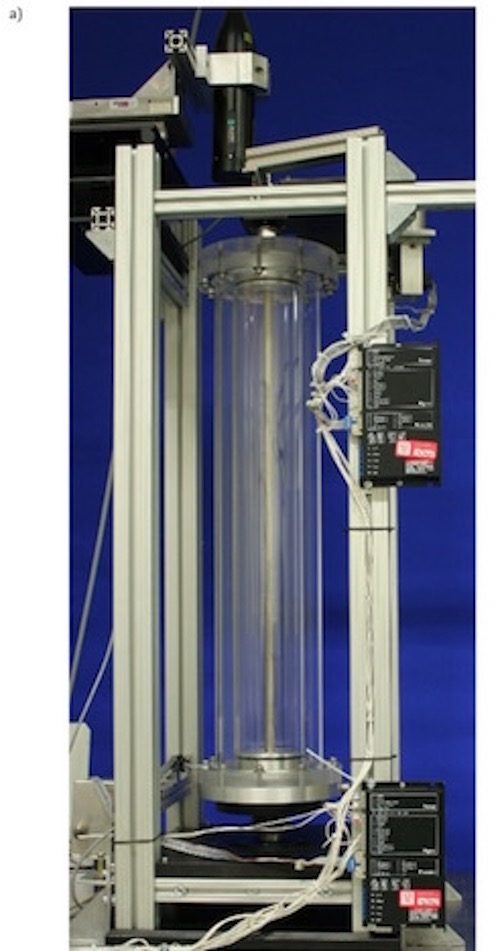
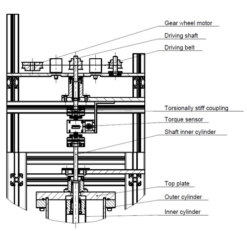
Due to optical and geometrical restrictions in the T2C2 - experiment, we constructed a second Taylor-Couette system, the so called Top-view-Taylor-Couette-Cottbus (TvTCC, see Figure 1a). There the outer cylinder and the top plate are made of acrylic glass to enable measurements of all three velocity components via LDA and PIV. As top and bottom boundary conditions, the end plates can be fixed at the inner or the outer cylinder or even be split into two rings rotating with the cylinders respectively. The inner cylinder is replaceable which gives access to radius ratios in the range from 0.1 to 0.8. As working fluids air, distilled water and silicon oils of different viscosities are used to reach Reynolds numbers up to 5∙105. Recently we upgraded the TvTCC-experiment by a new torque sensor. Hence, we can measure the angular momentum transport in fully turbulent rotating flows for different radius ratios while performing PIV measurements simultaneously. The set up is shown in Figure 2:
The shaft to shaft rotary torque sensor is mounted into the power train between the driving shaft and the inner cylinder shaft using torsionally stiff couplings. The driving shaft is accelerated via a belt using pulleys to avoid shear forces to the shaft itself and the sensor. It can measure torques up to 2 Nm with a precision of 0.1% of the maximum value. In contrast to the T²C² the torque is measured over the whole length of the inner cylinder to include end wall effects, which are always present in industrial applications. If a radius ratio of η = 0.5 is used the geometry of both systems is identical and comparisons allow us to isolate the influence of the end walls to the torque. To quantify the contribution of the system bearings to the torque signal also measurements with a non-filled gap are done.
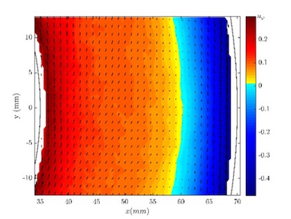
As shown in [1] the torque has a maximum at µ(η = 0.5) = -0.2. Using visualization techniques Merbold et al. [2] found out that the flow significantly changes, when the rotation rate is changed from co- to high counter rotation. To analyse the flow field quantitatively in the region of the torque maximum we performed PIV measurements in the radial-azimuthal plane for a constant shear Reynolds number of ReS=105 and rotation rates µ in the range of +0.2 to -0.6. In Figure 2a the temporal and spatial averaged azimuthal velocity component uφ (contour plot) and the 2D flow field (vectors) are shown for µ = -0.4. The black lines represent the cylinder walls. The inner cylinder (IC) is accelerating the flow in counter clockwise direction and the outer one (OC) in clockwise direction. Therefore, it exists a radial position inside the plane where the azimuthal velocity component vanishes. This so called neutral lin is indicated by the colour change from yellow to blue and separates the centrifugally unstable (IC) from the centrifugally stable (OC) part of the flow. Consequently, the angular velocity is radial stratified in the outer gap region while in the inner gap region a more inhomogeneous distribution appears.
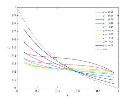
In Figure 3 the dimensionless radial profiles of the temporal and spatial averaged angular velocity = (ω-ω2)/(ω1-ω2) is pictured for different rotation rates µ. The radial coordinate is given by = (r-r1)/(r2-r1), which means = 0 at the inner cylinder and = 1 at the outer one.
For µ = +0.2 the flow is close to the Rayleigh stability (µ = η2 = +0.25) and thus the profile tends to the laminar one. When the rotation rate is decreased to the torque maximum (µ = -0.2) the profiles become flatter in the bulk flow indicating an strengthened transport of angular momentum due to an enhanced large scale circulation. For higher counter rotation rates the gradient of the angular velocity increases again in the region of the outer cylinder following the laminar profile shape more accurate. As already explained in case of the contour plot (Figure 3) the outer cylinder rotation stabilizes the flow for radial locations beyond the neutral line. Thus the investigation of the velocity field gives an explanation for the occurrence of the maximum in torque, which was already determined by visualisation techniques.
Bibliography:
- S. Merbold, H.J. Brauckmann, C. Egbers, Torque measurements and numerical determination in differentially rotating wide gap Taylor-Couette flo, Phys. Rev. E 87, 023014, 2013
- S. Merbold, A. Froitzheim, C. Egbers, Flow pattern and angular motion transport in a wide gap Taylor-Couette flow, TU Dresden, Strömungstechnische Tagung 2014, Schriftenreihe aus dem Institut für Strömungsmechanik Band 10, 2014


