Fluid Mechanics
Piston ring - oil transport FVV-Projekt
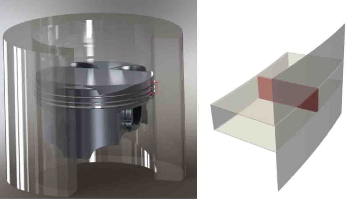
Oil that will be carried into the combustion chamber of Otto or Diesel engines increases the amount of particles; additionally it impedes the exhaust gas cleaning system. The upcoming emission limit values of future engines makes it necessary to have a reliable prediction of oil transport and consumption. The aim of our group is to compute the oil flow around an idealized top/second compression ring to estimate the oil consumption along this configuration (Figure 1).
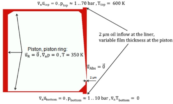
To achieve the numerical simulations we utilize the CFD software package OpenFOAM (OpenCFD-Ltd., 2014). Therefore we apply a compressible multiphase flow solver for immiscible fluids based on the volume of fluids method. The flow is purely pressure driven and will be set by a time depended boundary condition. Usually the pressure at the top land is greater than pressure at the bottom (second land), while the maximum difference is up to 70 bars. The volumetric concentration of the oil at the open boundaries will be fixed, due to the lack of information about the traversing oil from the bottom to the top. Figure 2 summarizes all the boundary conditions.
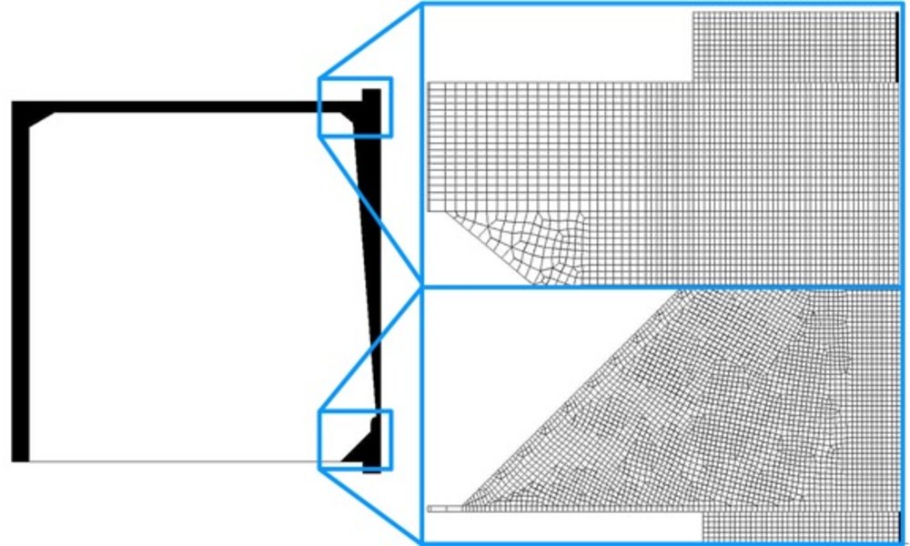
The main focus of the current research is to find an appropriate mesh motion method, which takes into account that the piston and piston ring are moving on independent displacement tracks. The mesh in the radial as well as axial direction will be squeezed and stretched. Therefore we developed two methods: The first method consists of a mesh deformation in radial direction and a cell annihilation method in axial direction like it is shown in Figure 3: Once a cell in this region becomes too small or too big it will be annihilated or split into two new ones. Thus there are no sharp jumps in the edge lengths of the cells. Additionally the mesh of the top land and second land stays undeformed and is connected via an AMI/ACMI-interface (Farrel, Maddison 2011). One big disadvantage is the changing number of cells during a simulation run, whereas OpenFOAM has no automatic load balancing routine. Hence during a parallel run it is necessary to distribute the cores manually. Another disadvantage is the necessity of having each addition/removal layer on a single core. This can lead to a non-homogenous number distribution among the cores and thus a low parallel performance.
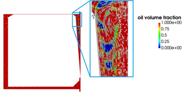
The second method consists of a mesh deformation method in both directions. Therefore no load balancing is necessary and long duration runs can be easily done. Under some circumstances it is slower than the first method, especially when the cells gets very small and decreases the time step. The method of mesh deformation in addition with an AMI-interface is a well-tested approach on this department (see journal bearing). Though the preparations for the final simulations are not finished yet, some preliminary simulations could be done (Figure 4): They show the presence of the strong vortices, which appear due the shearing between liner and piston. There are of interest because they are able to pull gas and oil against the main flow direction, even against strong pressure gradients.